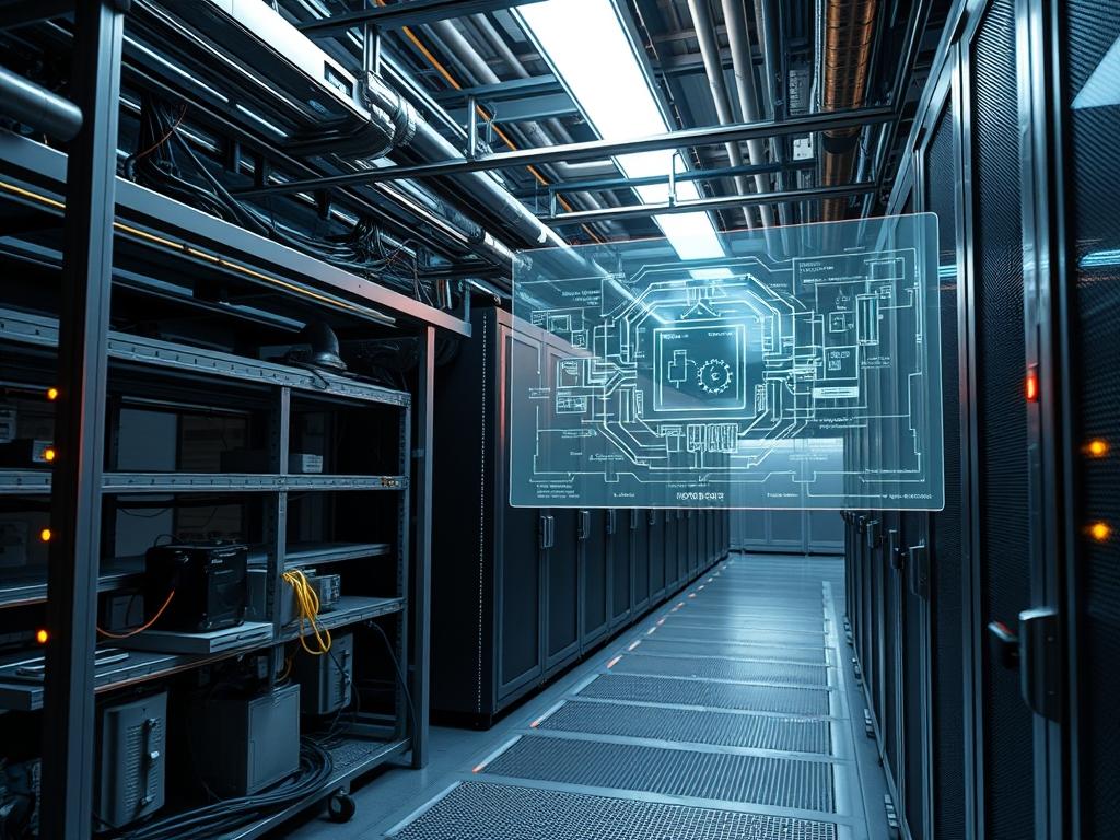
Data center lighting wattage represents a critical variable in the optimization of Power Usage Effectiveness (PUE) rankings. While the primary energy draw in a high-density facility is allocated to the IT load and cooling infrastructure, the parasitic draw of lighting systems contributes significantly to the total energy overhead. In a typical Tier III or Tier IV facility, lighting may account for 3 percent to 5 percent of the non-IT power consumption. This energy is not only consumed by the luminaires themselves; it is also converted into heat. This heat increases the thermal-inertia of the white space, forcing Computer Room Air Conditioning (CRAC) units to work harder to maintain the set point temperature. By reducing data center lighting wattage through High-Efficacy LED implementation and granular motion sensor control, administrators can reduce the heat load and improve overall system throughput. The integration of sensors into the Building Management System (BMS) allows for a logic-based illumination strategy where lighting is treated as a dynamic resource rather than a static utility.
Technical Specifications
| Requirement | Operating Range | Protocol/Standard | Impact Level | Recommended Resources |
| :— | :— | :— | :— | :— |
| Lighting Power Density (LPD) | 0.6 to 0.9 W/sq ft | ASHRAE 90.1 | 8 | Material: High-Efficacy LED |
| Sensor Latency | < 500 ms | DALI / BACnet | 6 | Logic: Real-time Controller |
| Signal Propagation | 24V DC / PoE | IEEE 802.3at | 4 | Unit: CAT6A STP Cable |
| Thermal Output | < 2.5 BTU/hr/W | NEC Article 645 | 7 | Environment: < 25C Ambient |
| Communication Bus | 1200 - 9600 baud | RS-485 | 5 | CPU: ARM Cortex-M4 |
The Configuration Protocol
Environment Prerequisites:
Implementation requires strict adherence to NFPA 70 (National Electrical Code) and IEEE 1100 (Emerald Book) for powering and grounding electronic equipment. The underlying control software must run on a hardened Linux distribution; typically RHEL 8 or Ubuntu 22.04 LTS. All automation scripts require sudo permissions for accessing the systemd service manager. Hardware dependencies include a DALI (Digital Addressable Lighting Interface) gateway and a centralized BACnet/IP controller. Ensure that all PIR (Passive Infrared) sensors are calibrated to the specific height of the rack enclosures to prevent signal-attenuation caused by cold-aisle containment structures.
Section A: Implementation Logic:
The engineering design centers on the concept of idempotent state management. The lighting system should not repeatedly send “ON” signals if the lights are already active; instead, it should maintain a state machine that tracks occupancy status across defined zones. By using encapsulation of lighting data within the BACnet protocol, the BMS can treat each light fixture as an addressable object. The goal is to minimize the total payload of the control network while maximizing the responsiveness of the sensors. High-efficiency LEDs reduce the initial wattage, but the motion sensors provide the exponential savings by ensuring that the duty cycle of each fixture is minimized. This reduces the thermal load on the facility, preventing the CRAC units from reacting to spikes in radiant heat.
Step-By-Step Execution
1. Hardware Initialization and Voltage Verification
Utilize a fluke-multimeter to verify that the line voltage at the lighting-distribution-panel meets the nominal specification of 277V or 120V. Check for consistent grounding to prevent electromagnetic interference with the low-voltage sensor lines.
System Note: This ensures the physical layer is stable before introducing logic controllers. High voltage fluctuations can cause flickering in LEDs, which increases the electronic noise and can affect the throughput of nearby data cables.
2. Controller Deployment and Service Activation
Install the lighting control software on the BMS server. Use the command sudo systemctl start lighting-manager.service to initiate the daemon. Verify the service status using systemctl status lighting-manager.
System Note: The lighting-manager service acts as the kernel-level interface between the high-level automation logic and the physical RS-485 or Ethernet bus. It manages the concurrency of sensor inputs across multiple data center halls.
3. Modifying Configuration File Permissions
Navigate to the configuration directory: cd /etc/lighting-control/. Adjust the permissions of the zone mapping file to allow the service to read the configuration: sudo chmod 644 zone-map.conf.
System Note: Proper file permissions prevent unauthorized modification of the lighting logic. Secure chmod settings are a baseline for facility security hardening, ensuring that physical access to the room is mirrored by secure digital access to the controls.
4. Sensor Calibration and Lux Threshold Tuning
Access the sensor interface via the fluke-multimeter in frequency mode or the vendor-supplied diagnostic-tool. Set the lux-threshold variable to 300. This ensures that if the room has natural light or enough ambient spillover from other zones, the LEDs will remain in a dimmed state.
System Note: Tuning the lux-threshold reduces the wattage by preventing unnecessary illumination. This logic is a key component in reducing the overall data center lighting wattage during daylight hours or low-occupancy periods.
5. Establishing the Off-Delay Timer
In the zone-map.conf file, locate the timeout_variable and set it to mimimum_5_minutes. Apply the changes by reloading the service with sudo systemctl reload lighting-manager.
System Note: The off-delay timer prevents rapid power cycling of the LED drivers. Rapid cycling can reduce the lifespan of the hardware and create unnecessary power surges on the lighting circuit.
Section B: Dependency Fault-Lines:
A major bottleneck in lighting efficiency is the physical placement of sensors. If a sensor is placed directly in the path of a high-velocity air stream from a perforated floor tile, it may undergo thermal-inertia fluctuations that trigger false positives. Furthermore, signal-attenuation occurs if the RS-485 control wire is run parallel to high-voltage power lines without proper shielding. This results in packet-loss within the lighting bus, causing lights to stay on indefinitely or fail to activate upon entry. Ensure that all control wiring is Category 6A shielded twisted pair (STP) to mitigate these risks.
THE TROUBLESHOOTING MATRIX
Section C: Logs & Debugging:
When a zone fails to respond, the first point of analysis should be the system logs located at /var/log/lighting-system/error.log. Search for the error string ERR_SIGNAL_TIMEOUT; this usually indicates a physical break in the DALI loop or a failed sensor.
If the sensors are reporting occupancy but no lights are engaging, check the payload delivery stats in the controller dashboard. High latency in the BACnet gateway often points to an IP conflict or a saturated network switch. Use ping -c 4 192.168.10.50 to test the connectivity to the lighting gateway. If the return trip time is over 100ms, the congestion is likely caused by excessive broadcast traffic on the management VLAN.
Monitor the thermal-inertia sensors within the racks. If the lighting system is contributing to a heat spike, the logs will show a correlation between zone_active_time and an increase in intake_air_temperature. In such cases, the wattage must be throttled via the pwm_dimming_protocol to 70 percent of maximum output to protect the IT assets.
OPTIMIZATION & HARDENING
Performance Tuning:
To improve the concurrency of sensor triggers in a large-scale facility, implement a staggered start-up sequence. Instead of all lights in a 50,000 square foot hall activating simultaneously, the controller should stagger the “ON” commands in 100ms intervals. This minimizes the inrush current and prevents voltage sags that can affect sensitive power supply units (PSUs) within the server racks.
Security Hardening:
The lighting network must be physically and logically isolated from the production data network. Use a dedicated VLAN with strict Firewall rules that allow only UDP port 47808 (the default for BACnet) to pass through the management gateway. Disable all unused services on the lighting controller, such as Telnet or unencrypted HTTP, to prevent lateral movement from a compromised facility device to the core infrastructure.
Scaling Logic:
Modern data centers utilize a modular architecture. When expanding the lighting system, use an idempotent configuration script that can push the same zone-map.conf settings to new controllers via Ansible or Puppet. This ensures consistency across the entire facility footprint. As the data center grows, the throughput of the management network must be monitored to ensure the additional sensors do not cause a packet-loss event on the primary management bus.
THE ADMIN DESK
How do I reset a non-responsive motion sensor?
Access the terminal and run sudo lighting-tool –reset
Why is the data center lighting wattage higher than the design spec?
Check the lux-threshold settings. If the sensors are set too low; they will keep lights at 100 percent even during maintenance. Ensure the pwm_dimming is active in the configuration to allow for 80 percent output.
Can I integrate the lighting with the Fire Alarm System (FAS)?
Yes. The FAS should have a dry contact relay connected to the BMS. When the relay closes; it triggers a high-priority override in the lighting-manager.service to set all zones to 100 percent brightness.
What causes the lights to flicker when the CRAC units start?
This is usually caused by voltage sag or poor isolation between the lighting and mechanical power feeds. Verify that the lighting is on a Phase-Balanced circuit and that the LED drivers support wide-input voltage ranges.
How do I monitor the energy savings in real-time?
Use the BMS dashboard to track the kW/h consumption of the lighting circuits. Compare this data against the Occupancy_Log to calculate the efficiency gain of the motion sensor logic versus a static 24/7 lighting schedule.

