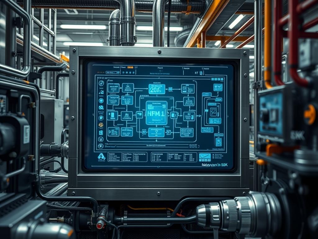
The rear door heat exchanger represents a critical evolution in high density data center thermal management; it addresses the physical limitations of traditional air cooling by relocating the heat rejection surface directly to the rear of the server rack. As compute densities exceed 20kW per cabinet, standard perimeter cooling units struggle with airflow bypass and significant thermal gradients. The rear door heat exchanger functions as a specialized radiator that captures heat generated by the server payload before it enters the room environment; this creates a near neutral thermal footprint within the facility. Within the technical stack, this hardware sits at the intersection of facility water infrastructure and IT equipment. It serves as an idempotent thermal barrier, ensuring that regardless of the computational throughput or transient spikes in CPU load, the exhaust air remains at or near the supply temperature of the room. This architectural shift significantly reduces the energy overhead associated with high velocity fans and large scale air handlers, optimizing the overall Power Usage Effectiveness.
TECHNICAL SPECIFICATIONS
| Requirement | Default Port/Operating Range | Protocol/Standard | Impact Level (1-10) | Recommended Resources |
| :— | :— | :— | :— | :— |
| Coolant Fluid | 18C to 27C (W3/W4) | ASHRAE TC 9.9 | 9 | Treated Water/Glycol |
| Flow Rate | 8 to 20 GPM | ASME B31.1 | 8 | Variable Speed Pumps |
| Sensor Data | Port 161 (SNMP) / 443 | MQTT/Modbus TCP | 7 | 2GB RAM / Dual Core |
| Pressure Drop | 5 to 15 PSI | ISO 2858 | 6 | Type L Copper / SS |
| Thermal Capacity | 30kW to 60kW | UL 60950 | 10 | Aluminum/Copper Fin |
THE CONFIGURATION PROTOCOL
Environment Prerequisites:
Successful deployment requires integration with a secondary cooling loop and a robust Building Management System (BMS). Hardware dependencies include secondary piping with flexible-braided-hosing and no-spill-quick-disconnects. Software requirements involve a Linux-based monitoring gateway running Ubuntu 22.04 LTS or higher to aggregate sensor data. Ensure all installers hold ASME plumbing certifications and that the network switch provides VLAN isolation for the thermal management plane. User permissions must include root access on the gateway and admin credentials for the BMS Modbus registers.
Section A: Implementation Logic:
The engineering design relies on the principle of thermal-inertia and efficient heat transfer through liquid mediums. Air, as a low density fluid, requires massive volumes to move equivalent heat energy compared to water. By employing a rear door heat exchanger, we utilize the server fans to push hot exhaust through a liquid-filled coil. The implementation logic treats the rack as a closed thermal encapsulation unit. This reduces the latency of heat rejection; the thermal payload is captured inches from the source rather than meters away at a perimeter unit. This design minimizes the impact of signal-attenuation in thermal sensors by keeping the Delta T localized. By maintaining a supply water temperature above the room dew point, we eliminate the risk of condensation, adhering to an idempotent cooling cycle where the objective is sensible heat removal without latent heat complications.
Step-By-Step Execution
1. Physical Mounting and Hinge Alignment
Physically secure the heat-exchanger-frame to the rear of the server cabinet using M6-torx-screws. Ensure the internal hinge mechanism allows for a 135 degree opening radius without putting tension on the coolant-feed-lines.
System Note:
This action impacts the physical integrity of the rack structure. Improper alignment can lead to mechanical stress on the secondary-loop-manifolds, potentially causing a physical bottleneck or structural failure during High-Availability (HA) maintenance windows.
2. Hydronic Connection and Pressure Testing
Connect the supply-hose and return-hose to the CDU-manifold using NPT-threaded-couplers. Perform a hydrostatic pressure test at 1.5 times the operating pressure for 30 minutes.
System Note:
This verifies the seal integrity of the hydronic circuit. Using a fluke-multimeter with a pressure transducer, monitor for any drop in pressure which would indicate a leak in the coil encapsulation, preventing potential catastrophic failure of the IT payload.
3. Sensor Deployment and Gateway Configuration
Install immersion-temperature-probes at the supply and return headers and thermistor-strings across the rear face of the door. Connect these to the logic-controller via RS-485 wiring.
System Note:
This enables the collection of raw telemetry. The logic-controller converts analog signals into digital payloads. Use systemctl-start-telegraf to begin the ingestion of thermal metrics into the time-series database.
4. Logic Controller Network Provisioning
Assign a static IP address to the thermal-management-unit. Edit the configuration file at /etc/sysconfig/network-scripts/ifcfg-eth0 to define the gateway and subnet mask.
System Note:
This establishes the communication path for the cooling control loop. Proper encapsulation of this traffic in a management VLAN prevents packet-loss or interference from the broader production network, ensuring high-throughput for monitoring data.
5. Flow Control Calibration
Access the actuator-valve settings via the web interface and calibrate the flow coefficient (Cv) based on the current rack wattage. Use chmod-755 on the local calibration scripts to ensure they are executable by the service account.
System Note:
This step fine-tunes the thermal response time. By adjusting the valve position, the system manages the water throughput to match the heat load, optimizing the power consumption of the primary cooling pumps.
Section B: Dependency Fault-Lines:
The primary failure point in a rear door heat exchanger setup is the air-locking of the heat exchange coil. If air is trapped in the upper registers of the aluminum-fins, thermal-inertia is compromised, leading to hot spots. Another significant bottleneck is the scaling of the internal pipe walls if the water chemistry is not maintained; this increases signal-attenuation in pressure sensors and reduces overall throughput. Furthermore, library conflicts in the python-modbus stack on the monitoring gateway can lead to intermittent data gaps, causing the BMS to trigger false-positive alarms regarding cooling capacity.
THE TROUBLESHOOTING MATRIX
Section C: Logs & Debugging:
When diagnosing efficiency drops, first examine the logs located at /var/log/thermal/cooling-service.log. Look for error strings such as ERR_FLOW_RATE_BELOW_THRESHOLD or WARN_DELTA_T_LIMIT_EXCEEDED. If the physical sensors show a discrepancy, use a fluke-62-max infrared thermometer to verify the surface temperature of the return-manifold. If the BMS reports a “Signal Lost” status, check the RS-485 wiring for a ground loop or electromagnetic interference. Use the command tail-f-/var/log/syslog while restarting the snmpd service to identify any handshake failures between the heat-exchanger-controller and the aggregation layer. Visual cues such as a blue LED on the control-logic-board indicate power, while a flashing amber LED typically signals a flow-meter out-of-range condition. Reference the specific error code pattern in the vendor-hardware-manual to correlate the flash frequency with the specific sensor failure.
OPTIMIZATION & HARDENING
Performance Tuning:
To maximize thermal efficiency, implement a dynamic flow control algorithm that utilizes predictive analytics based on IT workload. By monitoring the CPU-utilization at the rack level, the system can preemptively increase coolant throughput before the heat reaches the rear door. This reduces the latency of the cooling response. Tuning the PID (Proportional-Integral-Derivative) loop for the variable-frequency-drive on the pumps ensures that the system does not overshoot its set points, maintaining a steady state that minimizes mechanical wear on the actuator-valves.
Security Hardening:
The thermal management network must be treated as critical infrastructure. Disable all unnecessary services on the gateway using systemctl-disable-avahi-daemon and systemctl-disable-cups. Implement strict firewall rules using iptables or nftables to only allow incoming SNMP and HTTPS traffic from authorized management IP ranges. Change all default passwords on the logic-controllers and ensure that physical access to the manual-bypass-valves is restricted to authorized mechanical engineers through keyed-alike cabinet locks.
Scaling Logic:
Scaling a rear door heat exchanger deployment requires a modular approach to the hydronic infrastructure. As you add more units, ensure the primary-coolant-loop has the capacity to handle the increased GPM requirements without a significant pressure drop. Implement a “Pod-based” architecture where each row of racks has its own Coolant-Distribution-Unit (CDU). This limits the blast radius of a potential leak and allows for maintenance on one section of the data center without impacting the thermal stability of the entire facility. Use a decentralized control logic where each door operates autonomously but reports to a central orchestrator; this ensures that a failure in the central monitoring stack does not stop the localized cooling function.
THE ADMIN DESK
How do I clear an AIR-LOCK-ERROR code?
Locate the manual-air-bleed-valve at the highest point of the rear door frame. Open the valve slightly using a flat-head-screwdriver until a steady stream of fluid appears; then close it securely and restart the monitoring-service.
What is the maximum allowable Delta T for the water loop?
In a typical high density environment, the Delta T (temperature difference between supply and return water) should stay between 5C and 10C. Exceeding 12C indicates insufficient throughput or a possible obstruction in the heat-exchange-coil.
How do I update the controller firmware safely?
Upload the .bin file to the /tmp directory on the gateway. Use the firmware-update-tool to push the image to the logic-controller over the network. Always perform a backup of the current config-xml before initiating the update.
When should I replace the flexible-braided-hosing?
Inspect hoses Every 24 months for signs of brittleness or kinking. Replace immediately if any bulging or weeping is detected at the swivel-fittings. Standard service life for high quality EPDM or reinforced hoses is 5 to 7 years.
Why is my sensor data showing high latency?
High latency in thermal reporting is often caused by excessive polling rates on the Modbus-TCP gateway. Increase the polling interval to 5 seconds and ensure the network-switch is not dropping packets due to congestion on the management VLAN.

